This page documents a privately purchased "Harrison Series Ten" mixing console and serves non-commercial purposes only.
The manufacturer was contacted but could not provide any documentation.
All information, circuit diagrams, texts, photographs, drawings, and videos presented here were created by me. They are intended exclusively for the repair, restoration, and technical documentation of historic audio equipment, as well as for the modernization of its digital components.
All ROM images provided here were created by dumping EPROM chips. The firmware contained in these images belongs to Harrison Audio (Harrison Systems) and is provided solely for documentation, archival, research, and learning purposes.
Please note: I am an amateur in electronics and have no formal qualifications. Although I have reviewed the information carefully, I cannot guarantee its correctness. Should you find a mistake, I would be grateful if you informed me via email. As you can imagine, this is a long-term project. Since I work full-time as a caregiver at Schloss Hoym, my free time is quite limited.
Holger Marienberg, August 2025
In memory of my brother and mentor,
Steffen Marienberg (September 30, 1961 – August 19, 2025)
Diploma Engineer in Automation of Process Engineering
September 28, 2025
- Software:MCU 8051 IDE added
- Documents:Hardware updated
September 14, 2025
- Hardware:Channel Frame updated (complete)
- Documents:Schematics updated
September 3, 2025
- Documents:Data Sheets divided into Hardware/Software/Protocols
- Resources:JUCE added
- About:updated
August 31, 2025
- Hardware:Anacapa PSU updated (complete)
- Hardware:Channel Frame added (in progress)
- Documents:Data Sheets updated
- Documents:Schematics added
August 24, 2025
- Hardware:Anacapa PSU added (in progress)
- Documents:Data Sheets added
- Resources:External links added
The dream that wasn't a dream
In 1990, I bought a record that continues to influence my life to this day – Amarok by Mike Oldfield. This album represents
the "Holy Grail" for me in terms of creativity, complexity, dynamics, and sound quality.
Many years ago, I read that Mike Oldfield used Harrison's Series Ten mixing console for this album (and others, such as Islands
and Tubular Bells II). But owning a studio console of that class was simply unimaginable at the time.

Over the past 20 years, through working with my brother Steffen and developing our modular synthesizer, I've gained extensive experience in analog and digital circuit design, as well as programming in assembly language and high-level languages such as C and C++.
One day, I remembered the Series Ten and started looking for information about it. I was completely surprised to discover that
CML in Putzbrunn was offering a used Series Ten at a price that was actually within my reach. I thought about it for a few
days – and then I bought it.
At that price, I had no illusions that I’d get a fully functional console that I could just plug in and start using. Its power
consumption must be enormous. Besides, there’s hardly any information available online, and Harrison wasn't able to help me either.
In any case, I’m sure I’ll have a lot of fun and stress over the next few years researching, reverse-engineering and repairing the Series Ten.
Now the battleship is standing in my living room – and in the small town of Hoym, Saxony-Anhalt, I’m now officially regarded as a lunatic.

August 2025
The Harrison Series Ten
In 1985, Harrison introduced several revolutions with the Series Ten, the world’s first fully automated analog mixing console with digital control.
The first revolution consisted of complete recallability and automation of all parameters.
For the first time, all parameters of a mixing console could be stored and recalled. Competing systems of the era typically supported automation only for level and mute, but nothing beyond that.
As far as I can remember, Mike Oldfield mentioned in an interview that he mixed the 1983 album Crises using a Neve 8108 console and the NECAM automation system. However, NECAM only supports fader automation. To automate panning as well, Oldfield used a clever trick: he sent a signal to two identically set channel strips, with one panned hard left and the other hard right. The pan could then be controlled via the fader ratio between the two channels. However, this required sacrificing an additional channel.
On his 1987 album Islands, he made impressive use of the capabilities of his new Series Ten on the track "The Wind Chimes Part 2".
The second revolution was in design.
Dave Harrison broke new ground by employing potentiometers whose analog voltages were digitized by an 8-bit converter (AD7528). The potentiometers thus functioned solely as control inputs and were not part of the audio path. Unlike analog synthesizers - Dave Smith had already applied this principle in 1978 with the Prophet 5 - Harrison reduced the number of potentiometers per channel strip to five. Instead, miniature pushbuttons were used to select different functional blocks. Depending on the selection, the digitized values of the potentiometers were assigned to the chosen block.
The extremely flexible routing of the channel strip was implemented using analog multiplexers of the 405x series. Unlike other consoles, which used push buttons integrated into the audio path, the routing section of a Series Ten channel strip is made up entirely of LEDs.
It should be noted that in analog polyphonic synthesizers such as the SCI Prophet 5, the Oberheim OBX(a), or the Roland Jupiter 6/8, this principle had already been applied years earlier. Studio consoles, however, are subject to different quality standards - here the goal is not to generate sound but to process an external signal as cleanly as possible. For mixing consoles, this was pure science fiction at the time.
The third revolution was Harrison’s replacement of analog VCAs with digital-to-analog converters (DACs) functioning as DCAs (Digitally Controlled Attenuators).
Traditional VCAs process the audio signal directly, but the circuitry often introduces nonlinearities, distortion, noise, and other artifacts, meaning the result is not perfectly transparent. Harrison’s DAC-based approach worked differently: the signal was attenuated through digitally controlled resistor networks, leaving the audio path itself untouched by active control elements. This ensured that the original audio material was preserved, while still allowing precise, digitally driven automation. That’s why the Series Ten sounds both neutral and authentically analog.
However, when the company Harrison speaks of "just a handful of DCAs", this may be somewhat of an understatement: a single channel strip contains an entire arsenal of DAC0832 (8-bit) and DAC1232 (12-bit) converters. As a side note, the component packing density on a channel strip is extremely high.
Each channel strip contains two 80C31 microcontrollers for autonomous control, both clocked at 12 MHz.
In my 64-channel Series Ten, that means 128 microcontrollers are at work in the channel strips alone. Probably one of the MCUs is only used for controlling the fader module, while the other takes over the complete control of the channel strip. How the data exchange and communication with the master frame works, I do not know yet, as I am only at the very beginning of my research.
Harrison has always adhered to a philosophy of modular design.
The Series Ten is modular on every level and can be expanded with additional channel frames. Each frame follows the same principle. The meter bridge uses a carrier PCB with identical plug-in "light meter" modules for each channel, and the preamp stage is built the same way. Modules are interchangeable and can be replaced without soldering. Even the channel strip itself is internally divided: the circuitry for the eight aux sends, EQ, and other functions resides on plug-in boards.
Highest quality standards
The frames are partially welded and exceptionally robust, with power distribution implemented securely and cleanly, exemplary signal shielding, and PCB design that can rightly be called a masterpiece. While the technology may now be somewhat dated, its sonic quality is beyond dispute. All ICs are socketed, allowing easy replacement without soldering. With a set of spare modules, the Series Ten can be restored to full operation quickly and without a soldering iron.
And above all, it remains something truly different - and beautiful.
September 3, 2025
MCU 8051 IDE
After reading the EPROMs with a "Batronix Batupo II", I use the free MCU 8051 IDE to disassemble the code.
It is important to distinguish between the actual program code stored in the ROM and the assembly listing generated by a disassembler. While the program code represents raw machine instructions, the original assembler source code would also contain labels, directives, and comments.
For example, in the original source code, lookup tables may be defined using directives such as DB or DW. A disassembler, however, interprets these bytes as instructions and represents them as such in the assembly listing. As a result, these parts of the program code appear as confusing nonsense in the generated listing. This nonsense can contain supposed jump instructions, from which the disassembler derives misleading labels. At that point, it becomes very easy to lose track.
The following example comes from the UART ISR of the firmware "PN 0700-XMODS1C" of the slave processor on a channel strip:
Disassembled code                       Revised code

01  label7:              01  uart_07:
02  add A, #0Dh          02  add A, #0x0D
03  movc A, @A+PC        03  movc A, @A+PC
04  mov R0, A            04  mov R0, A
05  mov A, SBUF          05  mov A, SBUF
06  clr RI               06  clr SCON.0
07  mov @R0, A           07  mov @R0, A
08  xch A, 6h            08  xch A, 0x06
09  xch A, PSW           09  xch A, PSW
10  xch A, 7h            10  xch A, 0x07
11  reti                 11  reti
12  jb 22h, label8       12
13  add A, @R0           13  ;lookup table @0x00BF
14  add A, R0            14  DB 0x20,0x22,0x24,0x26,0x28,0x2A,0x2C,0x2E
15  add A, R2            15  DB 0x22,0x23,0x24,0x25,0x0A,0x0B,0x0C,0x0D
16  add A, R4            16  DB 0x0E,0x0F,0x10,0x11,0x00
17  add A, R6            17
18  ret                  18  ;@0x00D4
19  rl A                 19  uart_08:
20  add A, #25h          20  mov A, SBUF
As can be seen the disassembled code after line 11 makes little sense and without a label it is completely senseless.
The instruction "add A, #0x0D" adds 0x0D to the accumulator. Then, "movc A, @A+PC" adds the accumulator to the program counter to calculate the target address, and then loads the accumulator with the value at the calculated address. If the accumulator initially contained 0x00, the resulting address points to the start of a lookup table. Understanding this allows the disassembled code to be corrected.
For a disassembler, the hardest scenario is jumps whose targets are calculated at runtime. In this case, the code might only be understood by tracing it step by step within the IDE’s simulator. The following example comes from the "XMD218" firmware of the screen processor on the channel strip:
c0x3517:
    mov C, A.7
    anl A, #0x3F
    push ACC
    lcall c0x356F
    mov DPL, A
    pop ACC
    lcall c0x352C
    mov DPH, A
    clr A
    jmp @A+DPTR
Here, the low and high bytes of the data pointer are calculated by two subroutines. The accumulator is cleared, and a jump is performed to the computed address. Without a precise understanding of the protocol and the hardware architecture, it may not be possible to trace the code any further at this stage.
Fortunately, in this example, both subroutines contain simple lookup tables, and the accumulator has the same value for both, which is why I can easily reconstruct the jump addresses in this particular case. Furthermore, the instruction "anl A, #0x3F" makes it clear that each of the lookup tables holds at most 64 bytes. Tracing with the simulator is therefore unnecessary at this point.
c0x356F:
    inc A
    movc A, @A+PC
    ret

    DB 0x2B, 0x93, 0x87, 0xA3, 0xC8, 0xC8, 0x39, 0x2B
    ...

c0x352C:
    inc A
    movc A, @A+PC
    ret

    DB 0x35, 0x2E, 0x30, 0x2A, 0x32, 0x33, 0x34, 0x35
    ...
For example, if the accumulator contains the value 0x03, the DPTR will be loaded with the address 0x2AA3. Program execution will then continue at this address via the "jmp @A+DPTR" instruction. However, the disassembler cannot determine whether the contents at this address represent executable code or data. Consequently, the location may contain valid instructions, valid data, arbitrary data, or dead code. The “hidden” program code at address 0x2AA3:
jb 0x27.5, c0x2AC4
jb 0x27.6, c0x2AB2
mov DPTR, #0x0481
mov A, #0x01
lcall c0x578D
ret
A brief side note: In my own software I use computed jump addresses. For my favorite microcontroller, the ZNEO from Zilog, I wrote a small routine years ago that I called “Task Scanner”. This routine analyzed set bits and retrieved the corresponding jump addresses from a lookup table, which were then accessed using the JP (Rs) instruction. It was a multitasking routine only a few bytes long, which allowed me to enable or disable any routine from within any other routine, and each routine could also disable itself by clearing its own designated "task bit".
To reconstruct comprehensible source code from a complete firmware, I cannot merely read the disassembled listing line by line and must trace the code at specific points.
To create a clear representation of the code, I generate an empty .asm file and use the ORG directive to map each part of the code to its original address range. Since an 80C31 program always starts at address 0x0000 and the interrupt vectors are predefined, I already have several fixed, well-known entry points to work from. I replace labels with their corresponding addresses (e.g., c0x03C3:) and add comments to the code blocks.
I can safely transfer a code block as long as no unconditional jump, calculated jump, or RET/RETI instruction appears. Only then do I need to examine the following code more carefully to determine whether it makes sense or if it depends on a preceding conditional jump.
    ORG 0x0000
start:
    ljmp c0x036E

    ORG 0x036E
c0x036E:
    mov R0, #0x7F
;clear RAM
c0x0370:
    mov @R0, #0x00
    djnz R0, c0x0370
;init MCU
    mov 30h, #0x01
    mov SP, #0x33           ;stack pointer
    mov PSW, #0x00          ;program status word register
    mov 07h, #0x08
    mov TMOD, #00000010b    ;timer mode: 8bit auto-reload
    mov TH0, #0x7E          ;timer0, high byte
    mov TCON, #00010000b    ;turn on timer0
    mov IE, #10000010b      ;enable timer0 overflow interrupt
    clr TCON.6              ;turn off timer0
    orl PCON, #10000000b    ;double baud rate
    mov SCON, #10010000b    ;9bit UART, receiver enabled
    clr SCON.1              ;clear transmit interrupt flag
    clr SCON.0              ;clear receive interrupt flag
    setb IE.4               ;enable serial port interrupt
    mov P2, #00100000b      ;init port2
...
;wait for UART ISR to clear RAM address 0x30
c0x03C3:
    mov A, 0x30
    jnz c0x03C3
...
    jb 0x27.2, c0x04D3      ;points to valid code at
                            ;address 0x04D3
    mov DPTR, #0xE041
    movx @DPTR, A
    dec DPL
    movx @DPTR, A
    ljmp c0x04E5

;valid code
c0x04D3:
    mov A, 0x10
    anl A, #0x3F
    dec A
...
Once I have revised the disassembled code and added comments, I create a flowchart in OpenOffice Draw to provide a logical overview of the routine.
Although labor-intensive, this approach provides a welcome alternative to solely measuring the hardware and drawing schematics, but hardware reverse engineering is essential to determine which components are controlled by specific routines and how the flags in RAM are allocated.
Both the "Screen Processor" and the "Slave Processor" boards of a channel strip, which communicate with each other via UART, contain 27C256 EPROMs with 32 KB, making the firmware correspondingly large. While significant portions of the EPROMs appear to consist of lookup tables, the analysis is nonetheless expected to take several months.
74HC Series
- 74HC74Dual flip-flop
- 74HC109Dual flip-flop
- 74HC126Quad buffer 3state
- 74HC1373-to-8 line decoder with address latch
- 74HC221Dual monostable multivibrator
- 74HC2373-to-8 line decoder with address latch
- 74HC373Octal latch 3state
- 74HC374Octal flip-flop 3state
- 74HC3934bit counter
Analog-to-Digital Converters
Digital-to-Analog Converters
Diodes
- 1N1183APower silicon
- 1N2128APower silicon
- 1N5231B5.1V / 0.5W Zener
- 1N5245B15V / 0.5W Zener
- 1N5263B56V / 0.5W Zener
- 1N5352B15V / 5W Zener
- MR751Power silicon
Voltage Regulators
Memory
Microcontrollers
- 80C318bit microcontroller
Multiplexers
Operational Amplifiers
- LM324Quad OP-Amp
- LT1057Dual OP-Amp
- MC33078Dual OP-Amp
- NE5532Dual OP-Amp
- TL084Quad OP-Amp
- TLC274Quad OP-Amp
Others
Rectifiers
- MDA202GSilicon bridge rectifier
Thyristors
Transistors
- 2N2405NPN Transistor
- 2N2905PNP Transistor
- 2N2907PNP Switching transistor
- 2N6057NPN Power darlington transistor
- MJ15016PNP High-power transistor
MCS51 Family
MIDI
USB
USB MIDI
Anacapa Industries
"Model AI 213" Power Supply
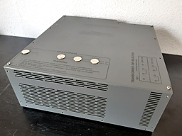
This power supply was most likely commissioned by Harrison, as it was also used in at least the 1983 MR‑4 console.
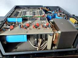
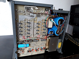
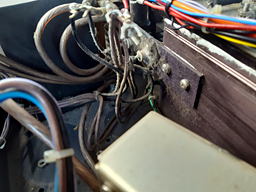
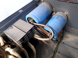
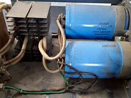
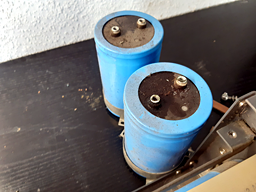
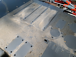
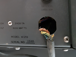
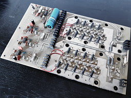
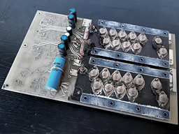
The first time I opened the power supply, there were no surprises. Many years of use had left the interior dirty and dusty. All electrolytic capacitors in the rectifier circuits have failed, some even leaking. The mechanical construction is of very high quality and extremely safe, with all components still in place. In this unit, the insulation of the power cord is dangerously damaged. All other internal wiring remains in good shape.
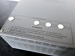
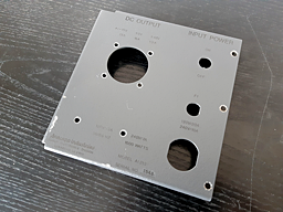
Each 16-channel frame of the Series Ten console requires its own dedicated power supply unit. This PSU operates from a 240VAC mains input (7A, 1600W) and delivers regulated DC outputs of ±15V (25A), +5V (15A), and +48V (0.5A). All output voltages are adjustable.
Transformer
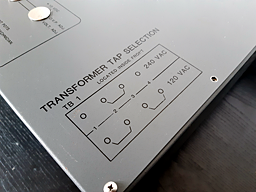
The transformer is marked “WTI 8750C”. The primary side consists of two separate windings, switchable for 120V (parallel connection) or 240V (series connection). For series connection, terminals 2 and 3 are linked; for parallel connection, terminals 1 and 3 as well as terminals 2 and 4 are bridged. The secondary side has four windings, three of which have a center tap. It weighs 15.5 kilograms.
The secondary side (no load):
| Terminal | Description | VAC |
|---|---|---|
| S5 | Winding end (meas. vs. S6) | 21 |
| S6 | Center tap | 0 |
| S7 | Winding end (meas. vs. S6) | 21 |
| S8 | Winding end (meas. vs. S9) | 21 |
| S9 | Center tap | 0 |
| S10 | Winding end (meas. vs. S9) | 21 |
| S11 | Winding end (meas. vs. S12) | 12 |
| S12 | Center tap | 0 |
| S13 | Winding end (meas. vs. S12) | 12 |
| S14 | Winding without center tap | 51 |
| S15 | Winding without center tap | 51 |
Secondary Windings Rectification
21VAC Secondaries
Each end of the winding is connected to the anode of a 1N2128A diode. The cathodes of the diode pairs form the positive output, which is connected to two 43,000µF/40V electrolytic capacitors in parallel. The negative terminals of the capacitors are connected to the center tap of the corresponding winding.
12VAC Secondary
Each end is connected to the anode of a 1N1138A diode. The cathodes form the positive output, which is connected to a single 82,000µF/25V electrolytic capacitor. Its negative terminal is connected to the center tap of the winding.
51VAC Secondary
This winding is connected directly to the mainboard of the power supply.
Mainboard
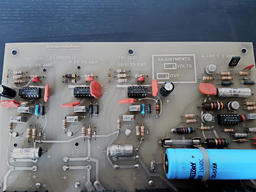
The "Model AI213" power supply for the Series Ten is based on the LM723 voltage regulator. The LM723 provides a precise reference voltage and controls the output via its internal error amplifier.
For the ±15V outputs, the reference is applied to the non-inverting input of the error amplifier through a 1kΩ resistor and a 220µF smoothing capacitor. The output voltage is fed back to the inverting input through a voltage divider, with a trimmer allowing fine adjustment.
The +5V output operates on the same principle, but since its voltage is below the LM723 reference of 7.15V, the reference itself is divided and adjusted via a trimmer before being applied to the non-inverting input. The inverting input still receives feedback from the output.
In essence, both regulator circuits are similar: for the ±15V outputs, the output voltage is divided for comparison, while for the +5V output, the reference voltage is divided.
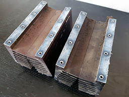
To handle higher load currents, several external 2N6057 Darlington transistors are connected in parallel and operate as series pass elements in an emitter-follower configuration. Low-value emitter resistors ensure equal current sharing among the devices, while heat is dissipated via two heatsinks.
For the ±15V and +5V outputs, overvoltage protection is provided by a crowbar circuit consisting of a reference Zener diode, a 2N2907 PNP switching transistor, and an MCR71-2 thyristor. The threshold voltage of the circuit can be adjusted using a trimmer. If an output exceeds this voltage, the thyristor fires and short-circuits the output, causing the supply fuse to blow and protecting the Series Ten from damage.
To generate a +48V phantom power supply, the transformer provides a 51V secondary winding. This AC voltage is converted to a raw DC voltage of approximately +50V using a bridge rectifier and two 530µF electrolytic capacitors. The operating voltage for the LM723 is derived via a 15V Zener diode.
Since the LM723 can only regulate voltages up to 37V at low currents, its output is not used directly. Instead, the IC controls a transistor stage via its Vz pin, consisting of Q24, Q25, and Q26.
The combination of Q24 (NPN) and Q25 (PNP) forms a complementary driver stage that translates and amplifies the LM723’s control signal, allowing the power transistor Q26 to provide the desired +48V output. The output voltage can be adjusted as needed.
Additionally, a non-adjustable crowbar circuit is included, based on a 2N2905 and an MCR106-3 thyristor, to protect the circuit in case of overvoltage.
Channel Frame
The channel frame is designed as a fully modular system, comprising four sections: meter bridge, preamps, channel strips, and fader modules. It requires two power supplies, with one dedicated exclusively to the fader modules.
All sections, except the fader section, are equipped with backplanes featuring DIN41612 socket strips. These allow the insertion of meter bridge modules, preamps, and channel strips. The fader section is unique because it has no backplane. Each fader module is connected directly to its corresponding channel strip via a dedicated ribbon cable. In this case, the function of a backplane is provided by a second ribbon cable, which appears to be designed as a data bus interconnecting the fader control on the channel strips.
As is typical for consoles of this class, the preamp and channel strip inputs and outputs are routed to the rear of the frame via DIN41622 connectors, providing maximum flexibility.
Power Distribution
The +48V, +15V, -15V, AGND, +5V, and DGND rails for the meter bridge, preamps, and channel strips are routed from screw terminals equipped with MR751 protection diodes to a PCB (1000-10252-1) and onward to the respective backplanes. The PCB features single-row 6-pin connectors with a 3.96mm pitch. Four wires per rail are soldered directly to the underside of the PCB, while the wires leading to the backplanes are soldered to the connector pins and secured with heat-shrink tubing.
This arrangement is appropriate because, once installed, the section requires no further modification, thereby also eliminating the risk of contact issues.
Backplanes
The following photos show all backplanes of a channel frame.
It is worth noting that both the backplanes for the Light Meter and the Preamps are equipped with multiple power connectors to handle the current demand and ensure reliable power distribution to the load. All traces of the individual rails are interconnected. Each pair of Light Meter boards is interconnected through their power connection.
It can be observed that a single power connector is provided for each group of four modules and channel strips.
Rear Panel Connectors
Each group of eight preamps is connected via three rear panel connectors, and each channel strip is provided with its own rear panel connector.
For detailed information, please consult the schematics.
Schematics
| September 14, 2025 | August 31, 2025 |


